
AC motor control circuits
Question 1:
Perhaps the most challenging aspect of interpreting ladder diagrams, for people more familiar with electronic schematic diagrams, is how electromechanical relays are represented. Compare these two equivalent diagrams:
First, the ladder diagram:

Next, the schematic diagram:

Based on your observations of these two diagrams, explain how electromechanical relays are represented differently between ladder and schematic diagrams.
Question 2:
Interpret this AC motor control circuit diagram, explaining the meaning of each symbol:
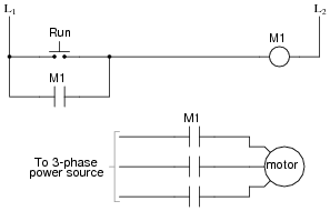
Also, explain the operation of this motor control circuit. What happens when someone actuates the "Run" switch? What happens when they let go of the "Run" switch?
Question 3:
Draw the necessary wire connections to build the circuit shown in this ladder diagram:
Ladder diagram:

Illustration showing components:

Question 4:
The simplest and least expensive style of electric motor control is the so-called across-the-line starter. Describe how this motor control circuit functions, and also define the word ßtarter" in this context.
Question 5:
Although äcross-the-line" motor control circuits are simple and inexpensive, they are not preferred for starting large motors. An alternative to across-the-line motor starting is reduced voltage starting. Identify some of the reasons across-the-line starting is undesirable for large electric motors.
Question 6:
A special type of overcurrent protection device used commonly in motor control circuits is the overload heater. These devices are connected in series with the motor conductors, and heat up slightly under normal current conditions:

Although the "heater" elements are connected in series with the motor lines as fuses would be, they are not fuses! In other words, it is not the purpose of an overload heater to burn open under an overcurrent fault condition, although it is possible for them to do so.
The key to understanding the purpose of an overload heater is found by examining the single-phase (L1 / L2) control circuit, where a normally-closed switch contact by the same name (ÖL") is connected in series with the motor relay coil.
How, exactly, do overload heaters protect an electric motor against "burnout" from overcurrent conditions? How does this purpose differ from that of fuses or circuit breakers? Does the presence of overload heaters in this circuit negate that need for a circuit breaker or regular fuses? Explain your answers.
Question 7:
The circuit shown here provides two-direction control (forward and reverse) for a three-phase electric motor:

Explain how the reversal of motor direction is accomplished with two different motor starters, M1 and M2. Also, explain why there is only one set of overload heaters instead of two (one for forward and one for reverse). Finally, explain the purpose of the normally-closed contacts in series with each starter coil.
Question 8:
The starter and overload heater assembly for an industrial electric motor is often located quite a distance from the motor itself, inside a room referred to as a motor control center, or MCC:
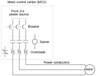
Since it is impossible for a technician to be in two places at once, it is often necessary to perform diagnostic checks on a malfunctioning electric motor from the MCC where the technician has access to all the control circuitry.
One such diagnostic check is line current, to detect the presence of an open motor winding. If a three-phase motor winding fails open, the motor will not run as it should. This is called single-phasing. A good way to check for this condition is to use a clamp-on (inductive) ammeter to check line current on all three lines while the starter is energized. This may be done at any location where there is physical access to the motor power conductors.
Suppose, though, you are working on a job site where single-phasing is suspected and you do not have a clamp-on ammeter with you. All you have is a DMM (digital multimeter), which does not have the ability to safely measure the motor's current. You are about to head back to the shop to get a clamp-on ammeter when a more experienced technician suggests an alternate test. He takes your DMM, sets it to the AC millivolt range, then connects the test probes to either side of each overload heater element, one heater at a time like this:

Across each overload heater element he measures about 20 mV AC with the starter engaged. From this he determines that the motor is not single-phasing, but is drawing approximately equal current on all three phases.
Explain how this diagnostic check works, and why this determination can be made. Also describe what limitations this diagnostic procedure has, and how a clamp-on ammeter really is the best way to measure motor line current.
Question 9:
A popular strategy for AC induction motor control is the use of variable frequency drive units, or VFDs. Explain what varying the frequency of power to an AC induction motor accomplishes, and why this might be advantageous.
Question 10:
Shown here is a typical set of "curves" for an overload heater, such as is commonly used to provide overcurrent protection for AC electric motors:
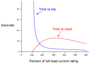
Why is there any time required to re-set an overload heater contact after a "trip"? Circuit breakers can be re-closed mere moments after a trip with no problem, and fuses (of course) can be replaced moments after blowing. Is this an intentional design feature of overload heaters, or just an idiosyncrasy?
Also, explain why the reset curve starts to decrease for currents above 300% of the motor's full-load rating. Why doesn't the reset time curve continue to increase with increasing fault current magnitudes?
Question 11:
Protective relays are special power-sensing devices whose job it is to automatically open or close circuit breakers in large electric power systems. Some protective relays are designed to be used directly with large electric motors to provide sophisticated monitoring, shut-down, and start-up control.
One of the features of these motor-oriented protective relays is start-up lockout. What this means is the relay will prevent someone from attempting too many successive re-starts of a large electric motor. If the motor is started and stopped several times over a short period of time, the relay will prevent the person from starting it again until a sufficient "rest" time has passed.
Explain why a large electric motor would need to "rest" after several successive start-up events. If electric motors are perfectly capable of running continuously at full load for years on end, why would a few start-ups be worthy of automatic lock-out?
Question 12:
Electromechanical relays used to start and stop high-power electric motors (called "contactors" or ßtarters") must be considered a possible source of arc flash. Explain why this is. What is it about the construction or operation of such a relay that invites this dangerous phenomenon?
Question 13:
There are several different methods of providing reduced-voltage starting for electric motors. One of them is the autotransformer method. Here is a diagram showing how this works:

"L1," "L2," and "L3" represent the three phase power supply conductors. Three sets of contacts (R, S, and Y) serve to connect power to the motor at different times. The starting sequence for the motor is as follows:
- 1.
- Motor off (R open, S open, Y open)
- 2.
- Start button pressed (S and Y contacts all close)
- 3.
- Time delay (depending on the size of the motor)
- 4.
- Y contacts open
- 5.
- Time delay (depending on the size of the motor)
- 6.
- R contacts close, S contacts open
Explain the operation of this system. How do the autotransformers serve to reduce voltage to the electric motor during start-up?
Question 14:
Identify at least three independent faults that could cause this motor not to start:
For each of the proposed faults, explain why they would prevent the motor from starting.
Question 15:
There is something wrong in this motor control circuit. When the start button is pressed, the contactor energizes but the motor itself does not run:

Identify a good place to check with your multimeter to diagnose the nature of the fault, and explain your reasoning.
Question 16:
Interpret this AC motor control circuit diagram, explaining the meaning of each symbol:

Also, explain the operation of this motor control circuit. What happens when someone actuates the "Run" switch? What happens when they let go of the "Run" switch?
Question 17:
Identify at least one fault that would cause the motor to turn off immediately once the "Start" pushbutton switch was released, instead of "latch" in the run mode as it should:

For each of your proposed faults, explain why it will cause the described problem.
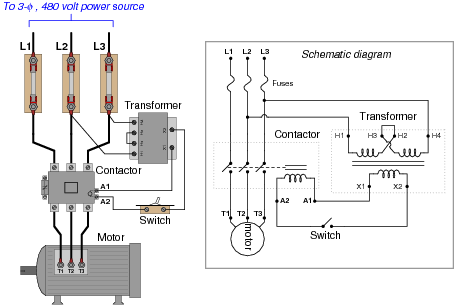
Question 18:
A very common form of latch circuit is the simple ßtart-stop" relay circuit used for motor controls, whereby a pair of momentary-contact pushbutton switches control the operation of an electric motor. In this particular case, I show a low-voltage control circuit and a 3-phase, higher voltage motor:

Explain the operation of this circuit, from the time the "Start" switch is actuated to the time the "Stop" switch is actuated. The normally-open M1 contact shown in the low-voltage control circuit is commonly called a seal-in contact. Explain what this contact does, and why it might be called a ßeal-in" contact.
Question 19:
An alternative to the conventional schematic diagram in AC power control systems is the ladder diagram. In this convention, the "hot" and "neutral" power conductors are drawn as vertical lines near the edges of the page, with all loads and switch contacts drawn between those lines like rungs on a ladder:

As you can see, the symbolism in ladder diagrams is not always the same as in electrical schematic diagrams. While some symbols are identical (the toggle switch, for instance), other symbols are not (the solenoid coil, for instance).
Re-draw this ladder diagram as a schematic diagram, translating all the symbols into those correct for schematic diagrams.
Question 20:
Draw the necessary wire connections to build the circuit shown in this ladder diagram:
Ladder diagram:

Illustration showing components:

Yes, the "Run" switch shown in the diagram is a SPST, but the switch shown in the illustration is a SPDT. This is a realistic scenario, where the only type of switch you have available is a SPDT, but the wiring diagram calls for something different. It is your job to improvise a solution!
Question 21:
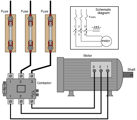
Examine this three-phase motor control circuit, where fuses protect against overcurrent and a three-pole relay (called a contactor) turns power on and off to the motor:
After years of faithful service, one day this motor refuses to start. It makes a "humming" sound when the contactor is energized (relay contacts close), but it does not turn. A mechanic checks it out and determines that the shaft is not seized, but is free to turn. The problem must be electrical in nature!
You are called to investigate. Using a clamp-on ammeter, you measure the current through each of the lines (immediately after each fuse) as another start is once again attempted. You then record the three current measurements:
Line Current
1 52.7 amps
2 51.9 amps
3 0 amps
Determine at least two possible faults which could account for the motor's refusal to start and the three current measurements taken. Then, decide what your next measurement(s) will be to isolate the exact location and nature of the fault.
Question 22:
Working on a job site with an experienced technician, you are tasked with trying to determine whether the line currents going to a three-phase electric motor are balanced. If everything is okay with the motor and the power circuitry, of course, the three line currents should be precisely equal to each other.
The problem is, neither of you brought a clamp-on ammeter for measuring the line currents. Your multimeters are much too small to measure the large currents in this circuit, and connecting an ammeter in series with such a large motor could be dangerous anyway. So, the experienced technician decides to try something different - he uses his multimeter as an AC milli-voltmeter to measure the small voltage drop across each fuse, using the fuses as crude shunt resistors:

He obtains the following measurements:
Line Fuse voltage drop
1 24.3 mV
2 37.9 mV
3 15.4 mV
Do these voltage drop measurements suggest imbalanced motor line currents? Why or why not?
Question 23:
One method of achieving reduced-voltage starting for large electric motors is to insert series resistances into each of the motor's power conductors. When starting, all power must go through the resistors. After the motor has had time to speed up, another set of ßtarter" contacts bypass line power around the resistors, directly to the motor windings.
Draw a diagram showing how this could be done for a single-phase electric motor, using two starter contacts: "R" for "run" and "S" for ßtart". Hint: you only need two contacts and one resistor!


